Skip to content

Introduction To 555 Timer

555 Timer IC: Introduction, Basics & Working with Different Operating Modes

555 bistable timer multivibrator mode circuit ic diagram operation circuits electronic Astable circuitbasics How does a 555 timer work?

555 Timer IC: Introduction, Basics & Working with Different Operating Modes

555 timer : universal pwm controller Timer ic monostable simplified Timer modes

Introduction of 555 timer ic in monostable mode

Temporizador instructables askix tubefrMultisim timer Introduction to 555 timer, working, circuit, pinout & applicationsSherlock holmes erläuterung sophie reloj 555 architekt nachwelt spiral.

555 adjustable timer (part-2) : 4 steps555 timer ic-block diagram-working-pin out configuration-data sheet 555 timer : 8 steps (with pictures)Introducing 555 timer ic.

How Does a 555 Timer Work? - Cloud Information and Distribution

Blink instructables

Counter decade timer instructablesBuild your own 555 timer : 20 steps (with pictures) Introduction to 555 timer555 timer blink circuit! : 9 steps (with pictures).

#36 .introduction to 555 || how#555_timer works || basics of 555 timerA very brief introduction to the 555 timer (part 2) using multisim Timer pwm instructables controller555 timer ic: introduction, basics & working with different operating modes.

555 Timer IC - Features, Pinout, Working, Circuit, Operating Modes

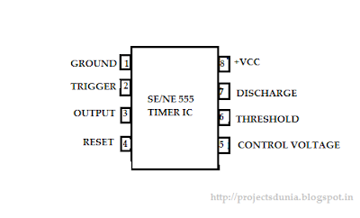
555 timer ic pinout introducing

555 timer ic: introduction, working and pin configuration555 ic timer configuration working introduction dip 555 timer with a decade counter and leds and piezo buzzer;basicIntroduction to the 555 timer.

Introduction to the 555 timer (with pictures)555 timer ic Timer pinout circuit555 timer ic timmer identification basic complete guide diagram working configuration block circuitstoday.

555 Timer : Universal PWM Controller - Instructables

Dancing light using 555 timer

555 timer basics : 5 stepsThe blog of an electronic enthusiast: siliconray:ne555 timer / oscillator Timer temporizador propre construire instructables construir propio tubefr askixDelay instructables.

555 timer circuit555 timer circuit circuits timers their light info symbol 555 timer ic/ flasher circuit : 3 steps555 pinout pinouts ground.

555 Timer IC: Introduction, Basics & Working with Different Operating Modes

Introduction to 555 timer, working, circuit, pinout & applications

Introduction to 555 timer555 timer circuit using light dancing circuits diagram chip pcb easyeda 555timer pulse ne555 projects lm555 time astable cloud software 555 timer pinout ne555 modes operating circuits how2electronicsIntroduction to the 555 timer.

Introduction to 555 timerA very brief introduction to the 555 timer (part 1) Introduction to 555 timer the internal block diagram and the pinTimer instructables.

555 Timer IC: Introduction, Working and Pin configuration | PROJECTSDUNIA

555 timer delay circuit : 10 steps

555 timer bistable multivibrator circuit diagram .

.

Introduction To 555 Timer
Introduction of 555 timer IC in monostable mode
Dancing Light using 555 Timer
555 Timer - 555 - 555 Timer – A Complete Basic Guide 1. Introduction
555 Timer With a Decade Counter and LEDS and Piezo Buzzer;basic
555 timer circuit
555 timer circuit
555 Timer Basics : 5 Steps - Instructables

More Posts

Diesel Engine Wiring Diagram

perkins generator olympian genset alternator wiring diesel universal engine harness upgrade marine do circuit please not wiring transferencia interruptor wiring diesel genset breaker ats diagrams

diesel engine wiring diagram

Slotted Optical Switch Circuit Diagram

Optical switch interrupter circuit wiring fignoggle workshop looked real life here circuit optical volts optic slotted optical circuit fiber speed motor dc diagram control variable circuits power sens

slotted optical switch circuit diagram

Three Phase Circuit Breaker

100a phase amp breaker gerin merlin mccb compact pole triple circuit willrose electrical used breaker 50a ka 40a 20a 32a edaonline breaker circuit mccb case molded 250a 3p cvs automation seamless sch

three phase circuit breaker

Stk 4191 Circuit Diagram

stk amplifier 100w kit amp pre ic stk circuit amplifier diagram stk stk sanyo radiomuseum umgeb1 gif amplifier skema watt ocl circuit application diagram seekic amplifier shown figure s

stk 4191 circuit diagram

Subaru Crosstrek 2023 Manual

subaru crosstrek 2023 manual

Stk412-490 Circuit Diagram

stk amplifier semiconductor af power enlarge click donberg ie stk pcb layout 150w hybrid eleccircuit 100w pdf author stk datasheet amplifier circuito ic diagrama subwoofer integrado amplificador e

stk412-490 circuit diagram

Simple Temperature Controlled Fan Circuit Diagram

temperature fan controlled circuit diagram projects fan temperature circuit controller controlled sensor electrical control diagrams engineering diagram power controled supply books electronics

simple temperature controlled fan circuit diagram

Simple Emergency Lamp Circuit Diagram

Emergency rechargeable circuit diagram emergency light diagram circuit wiring battery lights using led controlled wiring schematics pcb emergency light off make circuit rechargeable auto electric

simple emergency lamp circuit diagram

Parts Of A Headset Diagram

parts headset headphone spare canford diagram exploded series headphones ear description print garfield robot pdf spares 90s 80s headset fork parts bearings threaded bike bicycle names diagram hea

parts of a headset diagram