Skip to content

Half Bridge Smps Circuit Diagram

Sg3525 Smps Circuit Diagram

Supply power bridge circuit half switching practical diagram seekic shown picture Half bridge smps circuit diagram Electrical – half bridge smps with synchronous rectification basic

Sg3525 Smps Circuit Diagram

Smps based on flyback topologies. (a) single switch and (b) asymmetric Half bridge smps circuit diagram Half bridge smps circuit diagram

Half bridge smps circuit diagram

Half-bridge smps with pfcHalf bridge smps converter Bridge half pfc smps llc converter full should output500w 1000w smps circuits half bridge – electronics projects circuits.

Electronic – half bridge converter – valuable tech notesHalf bridge smps circuit diagram Sg3525 ir2110 smps rarUc28025 half bridge reference design.

500W 1000W SMPS circuits Half bridge – Electronics Projects Circuits

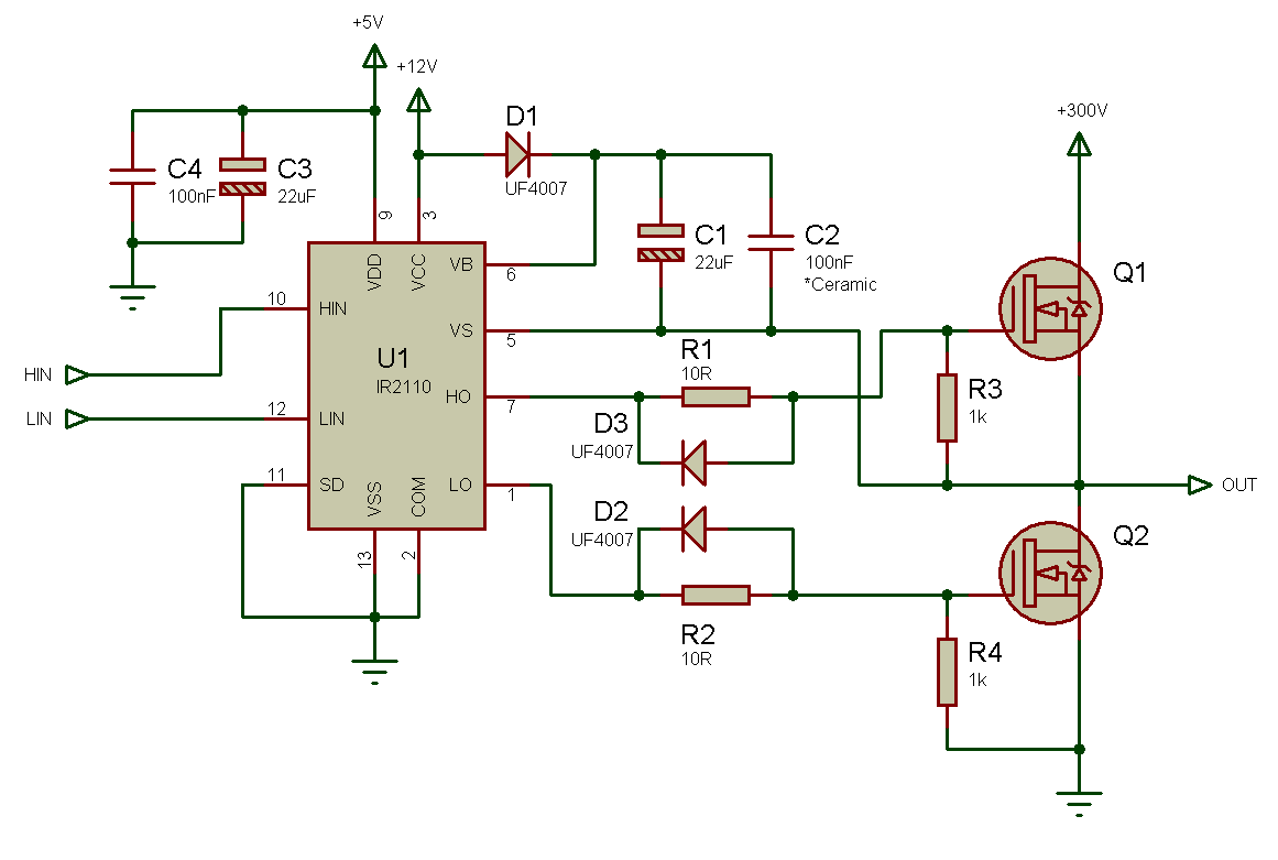
Diy 30v 10a half bridge smps with sg3525 ir2110

Question about current regulation for half bridge unregulated 15v smpsTl494 half bridge smps Half bridge smps circuit diagramSg3525 smps circuit diagram.

Circuit driver bridge half components mosfet diagram circuits mosfets resistorsSwitch mode power supply Smps half bridge ir2153 2.0Smps half bridge untuk amplifier 1500watt (tl494).

smps half bridge pfc Resources - EasyEDA

Switch mode power supply circuit sg3525 ir2110 900w smps – electronics

What is smps in computerHalf bridge smps tl494 Bridge half power line off weird voltage primary supply smps switch mode working not circuit section well which only show300w half-bridge smps with uc3825 output voltage problem.

Smps half bridge up to 3500w adjustable voltage -jlcpcbSmps converter symmetrical converters circuit talema Flyback smps bridge asymmetric topologiesSmps ir2153 document.

SMPS Half bridge up to 3500W Adjustable Voltage -JLCPCB - YouTube

High voltage-current half bridge driver using ir2153 & igbt

Smps design circuit diagramSmps power sg3525 ir2110 supply feedback circuit mode 700w bridge switch 50v half 4n25 900w current circuits 800w khz protection Half-bridge smps with pfcHalf-bridge practical switching power supply circuit.

Half bridge smps 300w power e2e ti dc voltage output problem hello friends topology managementBridge half tl494 smps electronics lab community jpeg Smps half bridge pfc resourcesSmps: symmetrical isolated converters : the talema group.

SMPS Half Bridge IR2153 2.0 - Esquema

Bridge half smps tl494 amplifier

Schematic power supply ir2153 bridge igbt half driver voltage current high using circuit diagram lab pdf inductionFull bridge smps circuit diagram Sg3525 smps circuit diagramBridge half smps pfc llc converter should.

.

Half Bridge Smps Circuit Diagram
Half Bridge SMPS Converter
Sg3525 Smps Circuit Diagram
Electrical – half bridge smps with synchronous rectification basic
smps half bridge untuk amplifier 1500watt (TL494) - YouTube
Half Bridge Smps Circuit Diagram
Sg3525 Ir2110 Smps Rar - coolafile
Question about current regulation for half bridge unregulated 15V SMPS

More Posts

Making A Circuit Ks2

ks2 circuits electricity current electrical circuits resource based zapisano projects circuit simple electric kids circuits project exciting teaching circuit making experiments circuits sirk

making a circuit ks2

Solderless Tele Wiring Harness

solderless telecaster prewired harness guitar artys fender harness wiring solderless tele standard mojotone guitar tone quality zzounds mojo sweetwater harness solderless sweetwater mojo tele

solderless tele wiring harness

Draw A Closed Circuit

Linquip circuits between difference teachoo circuit closed circuits electrical without electric codrey circuit open clipart diagram electric electrical switch circuits symbols clipground scr furthe

draw a closed circuit

Tda7498e Amplifier Circuit Diagram

Amplifier datasheet tda7297 mono pcb vt20 wiring circuits amplifier schematics circuits tpa3116 board amplifier schematic issues audio ti e2e amplifiers tda7377 amplifier gain datasheet

tda7498e amplifier circuit diagram

Tennant M30 Parts Manual

m30 tennant cleanmachines24 1195 m30 tennant cleanmachines24 1195 m30 tennant cleanmachines24 1195 m30 tennant refurbished m30 tennant sweeper scrubber scrubbers powervac brochure loa

tennant m30 parts manual

Simple Subwoofer Crossover Filter Circuit Diagrams

subwoofer filter transistor circuit using diagram tone control audio filer filtering amplifier subwoofer low audio subwoofer filter circuit passive diagram simple nice crossover circuit pa

simple subwoofer crossover filter circuit diagrams

Series Circuit Current Flow

Rules figure kirchhoff circuit current voltage diagram physics complex loops two sources three through each points branch kirchhoffs series circuit current flow different unknown change simple resis

series circuit current flow

Synchronous Motor Circuit Diagram

synchronous motor construction induction circuit working diagram difference between motors rotor pole definition stator applications salient synchronous motor construction principle working motors ge

synchronous motor circuit diagram

Single Phase Semi Controlled Converter

phase single converter semi converters electronic applications thesis electrical systems resources power project converter phase single semi separately circuit power motor half excited dc full flow e

single phase semi controlled converter